Tuesday, January 31, 2006

Starting to see the light?

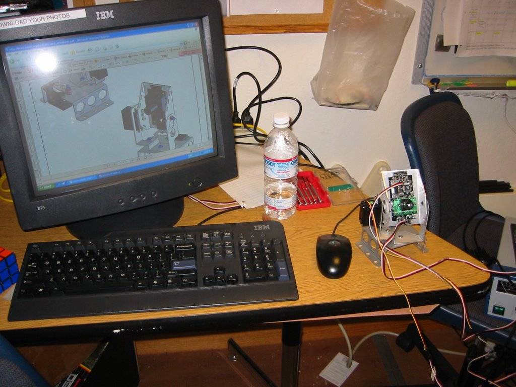
Y'all, good job today. Shirin, Chris and I worked on getting the turret to move a little less violently and prevent constant smackdown of the limit switches. With a very low value of pwm02 = 123 for CCW motion and a higher value of pwm02 = 142, we worked out the bias from the van door motor. Sort of . . .

For tomorrow: There's a zip file on the IDEO FTP site named 2006_EM_013006.zip. Download it if you're interested in seeing where we are.

So here's the deal. Rather than wading through the 'bells and whistles' version of the vision camera code, I've made an attempt to take the default code that we're familiar with and integrate it with the streamlined camera code. What does that mean?

1. You need to put in the default calibrated values into camera.h. You have those values now right?

2. I essentially took the 2006_EM_011506.mcp project and added the following files from the frc_camera_s.zip: camera.c, camera.h, terminal.c, terminal.h, serial_ports.c, serial_ports.h, and finally tracking.c and tracking.h which I actually don't use but are necessary for terminal.c to run.

3. You realize that you can learn and do a lot by just looking at TERMINAL.C. Please open it up and look at what it does. It's the function that prints the current state of a slew of camera values to the screeen every few seconds.

Okay, so what do you see printed to the screen?

- pan angle
- tilt angle
- pan error
- tilt error
- blob size
- confidence

What do all these things mean? Check page 34 and 35 of the CMUCam2 Workbook, and since all of you programming fans have read the ENTIRE manual already, this will be a good refresher .

So think about your basic strategy here. You just want to continue with your turret panning until all the following conditions are met (for example):

- your pan error is below a certain allowable value
- your tilt error is below a certain allowable value
- your blob size is above a certain desired value
- your confidence is above a certain desired value

Pan pan pan, search search search, and when all the above conditions are met. STOP EVERYTHING. STOP ALL YOUR MOTORS and shoot the darn ball!!

I hope 'nested if statement' is at the tip of your tongue!!! Is it?? Is it??!

The code I've included compiles, but since we don't yet have any hardware to plug it into, I do not vouch for its ability to actually do anything productive and I am not guilty if it results in personal harm or property damage.

Most interesting to look at user_routines_fast.c to start with.

Good luck,

Em

Sunday, January 29, 2006

Monday Madness!

Yo dudettes! I suspect that Doug and myself won't get to Castilleja until 6:30 pm or so but here are a few things to get started with:

1. Check out the code in the 'EMILY' folder on the desktop computer. It's the basic autonomous driving code that we wrote for the 2005 robot controller, rebuilt for the 2006 robot controller. That's what we've got downloaded to the robot controller right now so you can jump it in and out of autonomous and see what it does.

A few things to notice:

* Open up 'driving.c'. You'll find a few extra functions in it that are named 'TurretCW', 'TurretCCW' and 'TurretStop'. Do those make sense?

* Open up 'user_routines_fast.c' and under the User_Autonomous function, you'll find that I've added some test code for the turret motor. We haven't actually hooked up the turret motor (van door motor) underneath the camera platform yet so we should try.

BIG CAUTION BIG BIG BIG CAUTION: PLEASE *REMOVE* the LIMIT SWITCHES FROM THE PLATFORM before you try to run ANY CODE on the turret platform. If in doubt, call me. The van door motor has some SERIOUS torque and if the code is wrong (i.e. I'm not sure of the directions completely yet), it can result in the van door motor totally running the limit switches over, smushing them.

So, just pull the limit switches out of the holes in the platform for now, but don't unplug them from the robot controller. You can still used them.

* Hook up the speed controller (Victor 884) for the van door motor. You'll need some leads for power (black for ground, red for power - ask Julia who's been doing a fantastic job on the electronics board). You'll also need a PWM cable from the RC. Finally, you'll need to also make sure that the fan on top of the speed controller (Victor 884) gets power. Look at the other speed controllers for reference.

PLEASE DON'T BLOW THE SPEED CONTROLLERS UP. ALWAYS MAKE SURE THE FANS ARE ON. EACH VICTOR 884 COSTS $115.00. That means the electronics alone on our robot is worth well over $1000.00.

Yeah?? Okay, Doug and I will be there soon.

2. Debug the speed controllers on the electronics board. I suspect that might need more of Doug's help, but no worries.

Good luck and see you tomorrow!

Emily

Saturday, January 28, 2006

name the robot competition

just kidding
no competition
but we would love all input for possible robot names
no name is too ridiculous at this point
so get creative
get loving (for the yet-unnamed robot)
and get naming

go!

Friday, January 27, 2006

Making sure we have atleast a functional basic robot

Dearest Electronics Team,

Here are some important next steps:

1. VISION SYSTEM: PLEASE SAVE AND PRINT OUT ALL YOUR CALIBRATED VALUES. This is WORTH GOLD right now and all we have. Shirin or Sophia, I implore you to print out the values for RGB and error values etc. that allow your camera to work. Please do whatever you need - i.e. nail it to the ceiling if you have to. I don't want you to lose these values in the many versions of saved code you have on the desktop (ack, do we need to learn and use CVS in the future).

2. DEFAULT CODE: Let's make sure that we have atleast a moving robot. That would suck if we spent ALL our time trying ot get the camera code to work and didn't have a running robot (and if you look closely at the code, you'll see that in user_routines.c, that all the code that allows your robot to work has been commented out, which means you can't currently run the camera at the same time as your regular default code; gross). Let's make sure the deafult code compiles and that we can actually run our chassis on it - electronics board and chassis nearing completion, unfortunately a lot later than we had hoped :( :(

3. HELP FINISH UP THE ELECTRONICS SETUP: Bud is building a layout board for you. Jen now knows how to solder and Chrissy knows how to crimp lugs onto different sizes of wire. We should get this whole gig set up real soon and have all the wires connected except to the output actuators and sensors. I'm relying on you to get this done!! Jen also knows how to use heat shrink so let's try to use that rather than lots of electrical tape all over the place!! Oh right, you know what, Erin knows how to too because she did that in 8th grade tech challenge!!

We'll come back to the vision system when we have atleast a basic robot that works during the non-autonomous periods of the game. At this point, I *AM* concerned that if we focus all our time on vision tracking duirng the autonomous mode, we'll end up with a robot that sits there THE ENTIRE GAME. Should we not aim to atleast have a robot running during the non-autonomous part of the game??

That's just my opinion for all it's worth.

Thanks for listening to and surviving yet another Emily blogpost.

Thursday, January 26, 2006

hello? missing!

So today we are missing one-third of our subteam, i.e. Erin, due to a fractured ankle. OWCH! Ay, pobrecita!

We wish her a happy, speedy recovery.
Erin, we are thinking of you and miss your chatter and happiness.

Come back soon!

Wednesday, January 25, 2006

things to do next meeting....

* somehow mount the camera onto the van-door motor...
* ...see if tracking still works (if not, change code as necessary)

...and things to do later in the near-ish future
* program camera to move back-and-forth as part of the search algorithm (so robot can drive back-and-forth to find target, as the camera commands it to)
* make driving less sensitive
* program manual control of 'shooter'
* calculate what to do in passsive autonomous (where, how to move)

(Shirin is dancing with the camera as I type... very interesting... haha)

So apparently, today = happiness!

camera improvements

Remember how the camera was having problems with the search algorithm?
...Turns out we had commented something out that we shouldn't have,
and today we re-put it in, and VOILA! it worked! It steps, like Emily said it should!
And now, it tracks remarkably well, HOWEVER,
the servo is kinda of broken as Someman Who Need Not Be Named (cough) dropped the camera, and that certain servo comes apart at inconvenient times... however we realize we will not be using that certain servo because we will be using motors instead.

Whatever. It works!
This is a moment of which Shirin is very very proud, and insisted I record for all eternity. YAY!

Tuesday, January 24, 2006

Today we managed to get the camera working. We discovered that if you don't flip the camera switch, but just turn the power off, you don't have to re-load settings. Also, we got a motor to run instead of a servo. Our next goal is to make some sort of sketchy rig to mount the camera to the motor and see if we can get it to succesfully track with that. We plan to use switches (binary touch sensors) at either end of the span to tell the turret when to turn around.

Thursday, January 19, 2006

One Meeeeellion Dollars! Muahahahaha.


Nice work Sophia and Shirin. Camera is no simple task (it's the little dude to the right of the picture for you visitors to the site).

Next up . . . a suggestion. Dig into tracking.h I believe to figure out what you can do to just take out the changing of the tilt angle and just have it scan back and forth by panning. I haven't looked in deep but it looks like it's probably a nested FOR statement somewhere that makes it scan on one tilt angle, change tilt, scan on another tilt angle, change tilt etc.

See you tomorrow for a little bit!

m-uhahahahah

Tuesday, January 17, 2006

Potentiometer Fun!!!

We successfully hooked up a potentiometer (with help from the manual that Emily gave us) and coded so that we could see the value on the screen in a printf statement. Then, we used the value to control wheel speed and made the robot move forward or backward at various speeds based on how we turned the potentiometer.
Analog sensors will actually work! YAY!!!!!!!!!!!!!!!!!!!!
Teehee
-Sophia

Monday, January 16, 2006

Extra Extra! Read all about it! The GTS.

Not the celica GTS, but the gear tooth sensor. (Haha, I guess that's only funny to my bf since he owns the most clunker or clunker toyota celicas).

GREEAT sensor for tracking our yaw if we built a turret. Think tank like. Remember this post about the tank and turret?

Click here for '2006 Sensor Basic Operation' for more information about the GTS: Document on Sensors

Click here for the GTS data sheet (if you scroll to page 12, you'll realize that the GTS is about the size of a piece of snot and is mounted to the sensor strip already for you):
Allegro Microsystems Gear-Tooth Sensor

Remember that the US FIRST website is your oracle! You can pretty much find everything you ever want to know about any of these parts on that website, if you look hard enough!!

Good luck!

Emily

Monday's Happenings

The first thing we did today was to compile the 2006 default code so that we could run it on the 2005 RC. Thanks to Emily for her copius instructions! We also looked through interupts.c and the autonomous code that was already in user_routines_fast.c so we (Shirin and Sophia) fully understand the lovely timer mechinism. We did a little poking around to look at sensors that we could potentially use for distance. It appears that they gave you hook-ups for a gear-tooth sensor (gts) but not the actual sensor. We looked at the sensor that sees if light can get through (the name eludes me at the moment), but were a tad perplexed and had trouble finding any detailed documentation. Also, we bought a potentiometer (two, actually) so that we could play around with analog sensors. Neither Shirin nor I had brought our programming booklet, so our attempt to hook it up / program it properly was not successful. It did, however, change the value from what we initialized it as. It just would not continually returned 255. We hope to have it up and running tomorrow with help from our handy guide created by Emily.

Sunday, January 15, 2006

2006 RC vs. 2005 RC

As I blogged previously, the 2006 RC is not the same as the 2005 RC. The 2006 RC contains the PIC 18F8722 and the 2005 RC contains the PIC 18F8520.

No matter. I am pretty sure you can still compile 2006 default code for the 2005 RC and test it.

Here's what you would need to do - To compile this project to work with your 2005 FRC (18F8520) system do the following:

1. Select the correct device from the MPLAB IDE. Configure->Select Device->PIC18F8520

2. Replace the library file with the appropriate one. Remove the FRC_Library.lib file and replace it with FRC_Library_8520.lib OR Remove the FRC_alltimers.lib file and replace it with FRC_alltimers_8520.lib

3. Remove the 18f8722.lkr file and replace it with the 18f8520.lkr file

4. Rebuild your project and download the HEX file to your controller.

I pulled these instructions from the 2006 Default Code 'Other Files'. Under your project workspace (see the picture I posted below), the last line is a file called 'Using_Last_Years_FRC.txt. Open that and you'll find the same instructions.

Emily's Sample Code: long due explanation

I apologize that I haven’t had the chance to explain to all of you together what I did with the code in December to make it drive in a simple pattern in autonomous. I walked Sophia through the code that you should find in your email now; it’s a zipped file called ‘EM_011506_2006AUTO.zip’. First things first – copy this file onto the computer NOT ON THE DESKTOP, but in the C:\FRC2006.

When you open up the .mcp project file, you should see something like this on the left of your screen that shows you all the .h and .c files in your project. Try to compile it (CTRL+F10) – it should succeed.

Sorry it’s taken me so long. I had to take the autonomous code that I wrote for the 2005 RC and re-integrate it into the 2006 default code and that took me a little bit of time. If you’re not already aware of it, the 2005 RC uses the PIC18F8520 microprocessor and the 2006 RC uses the PIC18F8722. That’s why things aren’t going to be as straight forward as I hoped.


Here’s the gist of what’s going on with the autonomous / timer etc.

1. Open up interrupts.c. Look at how there are two functions that look awfully familiar: InterruptVectorLow and InterruptHandlerLow. Yes, I swiped and deleted them from user_routines_fast.c and put them in interrupts.c to keep all the interrupts stuff in one place.

2. I set up a GLOBAL second timer in interrupt.c according to the instructions in this white paper: http://www.ifirobotics.com/white-papers.shtml. This GLOBAL TIMER starts counting in seconds the MOMENT you start the robot. This is the BIG CLOCK I always look at when I’m trying to write code for time intervals within the existence of the robot being powered on.

3. Open up user_routines_fast.c and look at the function ‘User_Autonomous_Code’. That’s where I have a clock within a clock. Remember that in the background I have this GLOBAL CLOCK running in interrupts.c. So now, for autonomous, I have a mini clock that starts when I trick the robot into autonomous mode (with the plug that goes onto the operator interface). I mark when I jump into autonomous with a variable called ‘clockstart’. Do you see it? Then whenever I check the global clock, I store that value into ‘clock’. So now I can figure out how long I’ve been in autonomous mode for – with the variable deltaclock = clock – clockstart.

Does that make sense?

Here’s an example of how things could pan out:

I turn my robot on and the global clock starts running.

5 seconds into it, I trick the robot into autonomous. At this point: Clockstart = 5.

I check my clock every time I go into the loop, updating the variable ‘clock’ as necessary. Two seconds later, my variable clock = 7. Thus, at this point in time, deltaclock = clock – clockstart = 7 – 5 = 2 seconds, which is how long I’ve been in autonomous mode. Now I can do things like tell the robot to move forward for 2 seconds in autonomous mode and then move backwards for 2 seconds after that.

Hope this is good food for thought!

- Emily

Saturday, January 14, 2006

Monday

On Monday, programming is going to meet from 10-12 in the project room. Shirin and I (Sophia) are definitely coming; Christina, I really hope you can join us!

Saturday turns sunny

Hello. We brought in some heavy duty equiment today - Doug B (Tesla Motors) and welcome newcomer Eric Mac (Mindtribe). Doug continues to bring wonderful presents to support the hardware / software effort, aside from people like Eric Mac. Now we have a box full of tools just for the electronics team: crimpers, cutters, wire strippers, digital multimeters and such. Also, Doug pretty much bought one of every power strip product so there should be no excuses that you can't find an outlet to plug into now! Thanks to J Rock as well for loaning us the oscilloscope!

Eric and Doug made some serious headway on the camera - getting LabView 8.0 setup on the desktop computer. If we open up Labview, connect the camera to the computer, we can do a frame grab, pick a target, download that information to the camera, and then have it pick up that target. No working servos yet, but the camera can pick up and follow a target in its stationery field of view. Fantastic.

The oscilloscope also started giving us some well needed information about the PWM outputs coming out of the RC. Eeesh. We're only getting about a change of 25% in the PWM signal vs. the 3-100% duty cycle that the speed controller is supposed to be able to take. We thought it was the joysticks (nope) and now we think it might be the fact that GeneratePWMs only gets updated every 26.2 ms. We'd like to dig into the GeneratePWM function and see what it's all about since it's not giving us the expected output.

Em spent some time with Sophia explaining the timed autonomous code that was written in December. I will post this code on my FTP site for you guys to access and download and play with. Now Sophia understands what my autonomous code is doing, she should be able to explain to you what is happening. Again, ALL the computers (3 laptops, 1 desktop) should now have the newest version of MPLAB, C18 compiler, and the FRC2006 code, that successfully compiles!

Things to do next:

1. Programming team: Hook up an analog input i.e. potentiometer and try to read out the values (hint, using the printf to the terminal that we've always used). If you are going to Fry's also pick up the connector that goes with the 7.2 battery so we can set up the 2006 RC. Finally, can you hook up the 12V battery with the quick connects??

2. Em will post the autonomous code in a few days (probably by Monday night).

3. Look at and get the camera code running.

4. Set up the 2006 RC with some minimal inputs. Can we quickly mock up a surface to mount everything to for now? Velcro will do for now.

Cool. Thanks much!

- Emily

MPLAB, Default Code Setup!

Dearest programming team,

So here's the deal - does anyone remember way back when two months ago when I warned you that your 'location name' of your project file can't be more than 64 characters long? That was definitely the first culprit!! You really need to stick your project code here in the C:\ drive (or local drive) and NOT ON THE DESKTOP (that's where the location name becomes like a biggilion miles long).

So here's what we have now:

1. All four computers (including the desktop) are loaded with MPLAB, C18 compiler, and the IFI Loader for 2006 (yes, the 2005 IFI loader will not work).

2. All four computers have a copy of the 2006 default code in C:\FRC2006. I've successfully built and compiled the code on all four computers. DO NOT MESS WITH THIS COPY OF THE CODE. NO COPYING FILES OUT OF IT!! There's a 'shortcut icon' on the desktop to that location so you don't have to wade through 'My computer --> C:\ --> FRC2006' to get to it every single time.

3. Doug was working hard last night to install LabView 8 on the Desktop Computer. We're hoping to get the camera hooked up today and start looking at calibrating it for 'bench testing'. Getting it up and running might take a little while longer!

We're doing okay guys!

- Emily

Thursday, January 12, 2006

Friday: What you can do when Em is fixing computers

Yo. I'm sorry we couldn't solve the compiler problem today. Shirin and I discovered that the PIC processor in this years RC might be different from last year's (remember they said they added a s*load of memory?). Very scary. That is a serious problem I think. We'll see what we can do.

Okay, so here's what you can do while you're waiting. Please use your time wisely.

Look at the 2006 FIRST guidelines, tips & good practices. Yes, I printed out two copies of the booklet for you if you can't find it here.

I would like someone to put together an excel file that puts all the stall torque values IN THE SAME units so we can compare all the motors at face value. Also, I want the speed at no load converted from RPM to RPS (rotations per second) to degrees per second (Sophia, that's theta dot to you). Why????

We need to try to shoot the ball out from the spinning wheels at a certain speed. What is that speed? Can someone tell me the speed at which the spinning wheel (of radius r) connects to the ball? The fact that you have to find theta_dot is a really really good clue.

I can tell you that I've done all of this already, but of course, I can't just give it to you now just like that huh?

There's a lot of motor and sensor characterization we can do while we try to get the compiler up and running again. Please make use of your time.

Signing out since I need to write a personal statement tonight,

Em

Monday, January 09, 2006

Last post: No big-ass servos

To Sophia, who asked about using a big-ass servo essentially rotating the ENTIRE shooting system with the camera . . . No.

Remember that we can ONLY use the motors that are provided in our kits, and we don't have a big-ass servo included in the KoP. The only servos we have are the mosquito sized Hi-Tec ones that you so hate.

However, I can tell you that in this case, we can drive a turret like platform with a DC motor but use the gear tooth sensor, a very large potentiometer, some sort of homemade rheostat (do you know what that is?), or some other means to sense our rotational position, in combination with a simple switch to provide it with a physical starting position that it can initialize to.

Capiche? Let's ask Doug.

- Emily

Strategy, Autonomous and Coding

I just wanted to make sure that this all gets documented somewhere. The flowcharts that Ed walked you through were awesome . . .

Remember that autonomous doesn’t mean that it’s ALL autonomous. Remember that you’re not just DUMPING your robot onto an unexplored uncharted terrain like Mars or something. Your FIELD has specific dimensions, and your INITIAL position can only be one of three choices. You as a HUMAN BEING will know a lot about your robot that you can tell it in advance with simple digital I/O switches and not have to build sensor systems for (i.e. you’ll know how many balls you have in your robot at the start, so why bother having it sense that information when you can input it directly as a binary value?). Hence the hard coded switches that will drive your if/then/else statements.

Also, you know a lot of about your enviroment and the game pieces. What does that mean? If you can get your robot into a certain, let’s say 4’ X 4’ area on the field by just plan feedforward (i.e. no sensor information), then you can use your auto-targeting system to do the FINE CALIBRATION work for aiming. On a fully charged 12V battery (a voltage supply that is hopefully regulated – I’m checking), you should be able to tell your robot to drive forward for 3 seconds, turn left, and drive forward for another 3 seconds for example to get to your ‘target area’. We’ll have to experiment with the turning.

Remember, your human drivers can do the COARSE POSITIONING, so use your complex sensors (i.e. vision) ONLY FOR FINE CALIBRATION. Figure out what the bounds of COARSE POSITIONING are BEFORE you start trying to get your feedback system to do EVERYTHING for you. The truth is, trained humans are far better than feedback systems (see Wired Article on a well practiced high school team that beat an MIT student team that had a bad-ass system but little practice): http://www.wired.com/wired/archive/13.04/robot.html

Use your surroundings to guide you as much as possible in SIMPLE WAYS. My graduate school research work was all about sensors and feedback systems that were computationally simple and cheap, and THUS much more robust right off the bat. You can do a LOT with touch sensors for example. Sophia had a GREAT suggestion about getting the robot to drive up to the RAMP and sense it with simple touch sensor and then aiming from there. That’s a GREAT idea.

Please analyze your PLAYING FIELD: Please don’t tell me you don’t know anything, because you do, with a little bit of work.

1. How high up is the center of the hoop?

2. What angle is the hoop set up at?

3. If you are 10’ away in front of the hoop and you can shoot the ball out at 10 ft/s, what is the angle range that you can shoot at and still get the ball in, provided that you haven’t reached the peak of your trajectory.

4. Answer question 3 if you are 9’ feet away.

An excel spread sheet would be a GREAT idea (since we don’t know what our initial velocity will be). Or as Shirin pointed out, you can probably even write code to do this. (Oh man, you are totally making me want to bust out Matlab . . .)

This is a great analysis problem ;) See you tomorrow! Yah, I might just skip the talk at Stanford on ‘Engineering Education’ since this is way too much fun.

- Emily

Strategy Discussion (on Build Blog)

Shirin, Erin and Christina, for notes from today's discussion related to strategy, please go to the build blog or click on this link:

http://gatorbotics-build.blogspot.com/2006/01/ems-monday-night-build-strategy.html

- Emily

CMU Camera Workbook Link

Please read this during the weekend. I am going to aim to look at it by January 16.
http://www2.usfirst.org/2006comp/other/2006_CMUCam2_Workbook.pdf

If we are going to try to build an auto-targeting shooter, we really need to familiarize ourselves with this camera . . . like now.

- Emily

Saturday, January 07, 2006

Holy Smokes!

Someone's been working on a lot of good code already: http://www.kevin.org/frc/
You know the demo code I put together for you guys a while back on autonomous stuff and interrupts? Looks like they'll probably put something together in the next few days on this too!

Also check out this site for a basic description of this year's software: http://www.usfirst.org/robotics/2006/2006frcsoftwareoverview.htm

Check out the links on the side!

A few important things:

There's a blog specific to you here at http://gatorbotics-code.blogspot.com.

There's a blog for the mechanical and structural build at http://gatorbotics-build.blogspot.com.

And there's my friends of gatorbotics blog here: http://gatorbotics-friends.blogspot.com.

As well, I've posted some generic links to places like US FIRST and your own website for the time being. Let me know if there's anything else I can link to for you.

Welcome 11010100100

Hello Gatorbotics electronics and programming. We definitely picked up momentum at the end of last quarter. Let's keep it up!